
A patchbay in your home studio: what is it and do you need one?
Published on Friday 16 October 2026
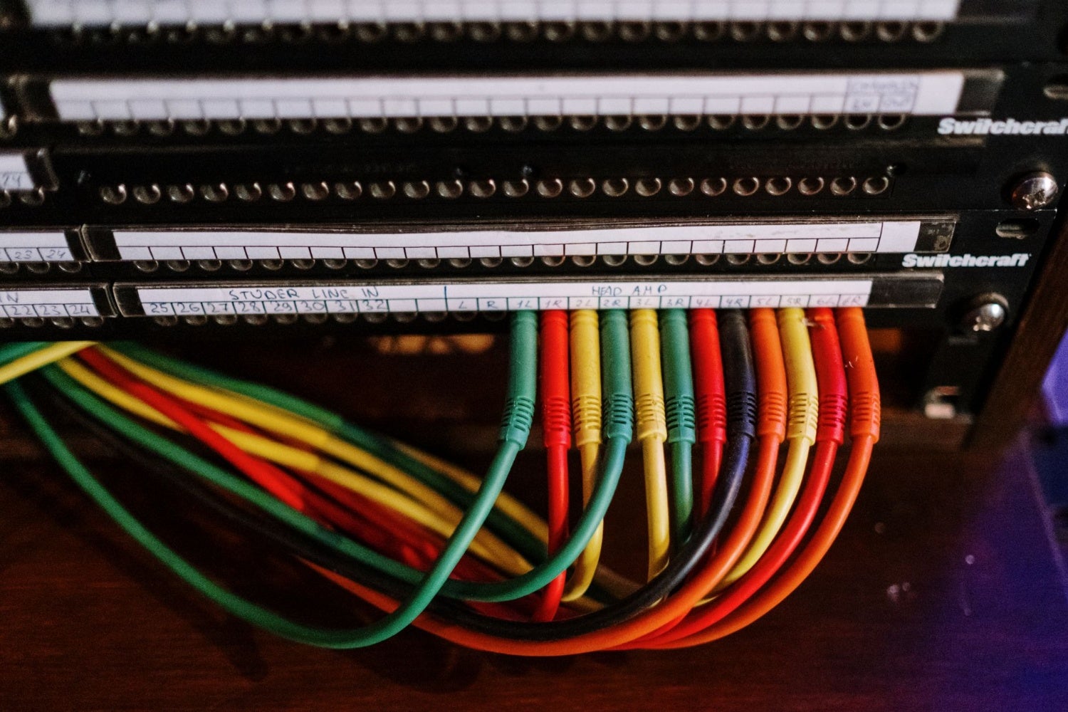
A patchbay brings all the inputs and outputs of your studio gear together on a single panel at the front of your rack, so you can use short cables to decide which signal goes where. It sounds like something reserved for big studios, but as soon as you combine a few pieces of outboard, a synth or two and a small interface, a panel like this quickly pays for itself in time saved and frustration avoided.
What exactly is a patchbay?
At its core, a patchbay is nothing more than a row of jacks on the back that are connected one-to-one to a row of jacks on the front. A standard 1U model for a 19-inch rack has 48 connection points: 24 on top and 24 on the bottom. The outputs of your preamp, the inputs of your compressor, the inputs and outputs of your interface: you connect everything neatly to the back once, and after that you never have to touch it again.
The routing happens at the front using short patch cables. Think of it as a railway marshalling yard: all the tracks run through it, and with a few simple sets of points you send each train down the track you want, without having to lay any new rails. The big advantage is that all inputs and outputs stay permanently connected. No more fumbling behind the rack with a torch, less wear and tear on jacks and cables, and fewer mistakes because you can see exactly what you’re patching.
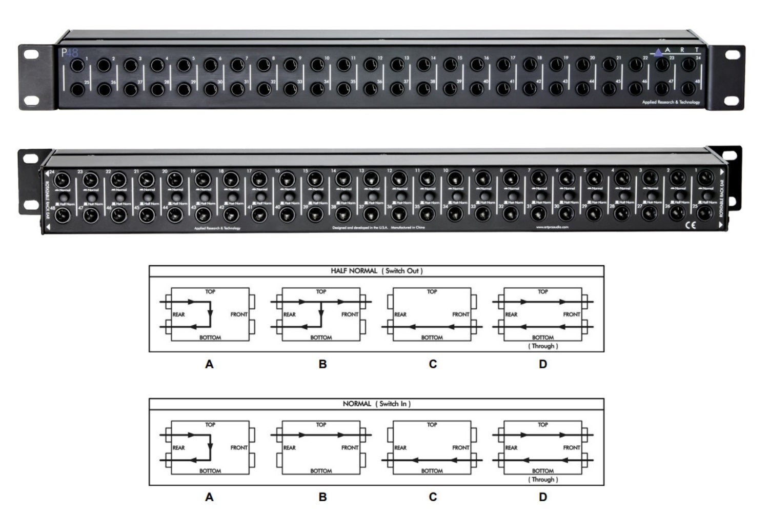
An example of a patchbay: the ART P48
When do you need one?
Do you have an audio interface and a microphone, and handle everything else with plug-ins? Then you can safely put off buying one, because in that case a patchbay is mostly just an expensive plank with holes in it. The tipping point is ‘outboard’, meaning all kinds of external effects, processors and so on. As soon as you own a standalone preamp, compressor or EQ that you don’t always want in the same place in the signal chain, the faffing about begins: today the mic cable needs to go straight into the interface, but tomorrow it has to run through the preamp and compressor to a line input.
The same applies if you need to connect synths and other sources to a small interface with just two inputs. With, say, three synths, a drum machine and a microphone, every spontaneous idea means first crawling behind your desk to fiddle about with cables. With a patchbay, everything simply stays connected and you choose at the front, in a matter of seconds, which source goes to inputs 1 and 2*. The rule of thumb: if you regularly find yourself re-patching your gear, it’s time for a patchbay.
*A small disclaimer here: patching microphones through a TRS patchbay while phantom power is in use carries a risk of damage. A TRS plug briefly shorts the contacts (tip/ring/sleeve) as it’s inserted and removed. If there’s 48V phantom power on the line, this short can damage microphones (ribbons in particular) or preamps. So switch the phantom power off first. On top of that, mics and line-level devices can’t simply share the same input without adjusting the gain and the mic/line switch on your interface. That last one isn’t dangerous if you forget, by the way.
» Expanding your interface: can you add more inputs and outputs?
» Try the Interactive Audio Interface Selection Guide
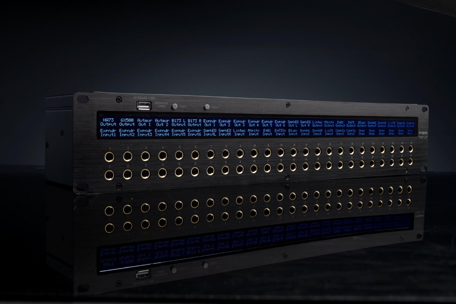
A patchbay with an LED display: no more sticking on labels
How to wire up a patchbay
First, the choice of connector. The two most common balanced types are the 6.3 mm TRS jack and TT (bantam). TT is considerably more compact, so far more connections fit into the same rack space, but it requires its own, smaller patch cables. For a home studio with a handful of devices, 6.3 mm is usually the logical choice; TT only really becomes interesting when you’ve got a mountain of gear and limited rack space. There are also versions with D-sub connectors or solder terminals on the back, incidentally.
Then comes the real work, on paper first. Write down all the inputs and outputs of your devices and decide on the default route for each pair: output on top, the corresponding input directly below it. Interface outputs above monitor inputs, preamp output above compressor input, and so on. Because the rear and front jacks correspond one-to-one, that diagram doubles as your wiring guide for the back and your labelling for the front. Set the mode for each channel and stick on some labels, because three months from now you won’t remember what jack 17 was.
» View all pro audio patch cables
Normalled, half-normalled and thru: how the routing works
The usual convention is that the top row holds the outputs of your devices and the bottom row the inputs. So the signal ‘drops’ from top to bottom. Even without a single patch cable at the front, your studio is already running in its default configuration, because a patchbay usually connects each top and bottom jack internally. How that connection behaves when you insert a plug at the front is determined by the mode.
With normalled (full-normal), a plug in either the top or bottom front jack breaks that connection, which is common for microphone lines. Half-normalled is the mode you’ll get the most out of, and it’s often the factory setting. A plug in the top jack taps off the signal while the internal connection stays intact: a copy you can listen to or send to a second device. A plug in the bottom jack breaks the connection and replaces the signal. In short: tap at the top, replace at the bottom.
Then there’s thru: top and bottom have nothing to do with each other and each carries its own signal, intended for sources you always route by hand anyway. How you switch between modes varies by model: some patchbays have a small switch for each channel on the front panel, while on others you flip a small circuit board around. That does mean removing the front panel, although the unit itself can stay in the rack.
 Want to turn LPs into MP3s? Here’s How to Digitise Your Vinyl
 How to Breathe: For Vocalists & Musicians
 Setting Up the Band with a PA System? Here’s What You Need to Know
 How to Tune Up & Play a Guitarlele
 Everything You Need to Know About Making a Podcast
 Want to Play Tight? Then Nail These Exercises
No comments yet...